
The Definitive Guide to UK Water Pipe Identification (BS 1710:2014)
1. Introduction: Why Identification Matters
Water pipe marking is not merely for convenience; it is a legal requirement under the Water Supply (Water Fittings) Regulations 1999 and Scottish Water Byelaws. Proper marking prevents cross-contamination, ensures the safety of maintenance personnel, and is critical for emergency response.
2. The Anatomy of a Pipe Marker
A compliant marker consists of three distinct elements: Basic Color, Safety/Code Color, and Directional Indication.
The Standard Color Palette
All water services use Green (BS 4800 12 D 45) as their base. The "Sandwich" method is then applied to specify the water quality.
| Water Type | Visual Code (Sandwich) | Technical Application |
| Potable (Mains) | Green / Blue / Green | Direct supply from a water undertaker. |
| Potable (Private) | Green / Grey / Green | Water from boreholes/wells treated to potable standards. |
| Non-Potable | Green / Grey-Black-Grey / Green | Rainwater harvesting or reclaimed "grey" water. |
| Fire Main | Green / Red / Green | Dedicated fire suppression lines. |

3. Critical Installation Rules
To be "better than the rest," your page must emphasize the placement logic that many installers miss.
-
Frequency: Markers must be applied at least every 500mm on concealed pipework.
-
The "Rule of Three": Always place a marker:
-
On both sides of a wall or floor penetration.
-
At every change of direction (elbows/tees).
-
Adjacent to every valve, pump, or appliance.
-
-
Legibility: Text must be in a contrasting color (usually white or black) and sized relative to the pipe diameter to ensure visibility from floor level.
4. Cross-Connection Prevention (The Safety Focus)
This is the most critical technical section. When integrating alternative water systems (like those found in your uploaded alternative_water_systems.pdf), the risk of "backflow" into the public mains is high.
-
Labeling Warning: Pipes carrying non-potable water MUST be clearly labeled "NOT FOR DRINKING" at every point of use (taps/outlets).
-
Backflow Protection: Your page should advise that any connection between a private supply (Grey/Green) and a mains supply (Blue/Green) requires a Type AA, AB, or AD air gap or a verifiable backflow prevention device.
5. Maintenance and Compliance Checklist
A high-quality guide provides actionable steps for the end-user:
-
Annual Audit: Inspect markers for fading or peeling (especially in UV-exposed areas).
-
Flow Verification: Ensure arrow directions match the actual hydraulic flow.
-
Update Records: Whenever a system is modified, pipe markings must be updated before the system is commissioned.
What is BS1710?
BS1710 is a set of standards used for marking pipes published by the British Standards Institute. BS1710 specifies the colours and supplementary information for the identification of pipes conveying fluids/gases in above and below ground installations. It also includes ducts for ventilation and conduits that carry electrical services. BS1710 is the most widely recognised system across the UK for identifying pipes and whilst these specific standards are not mandated by general UK law, some local authorities or governing bodies may specifically refer to the standards, therefore making them a legal requirement within the geographical jurisdiction or within a particular industry or context.
For help in understanding the legal implications see this article from the BSI
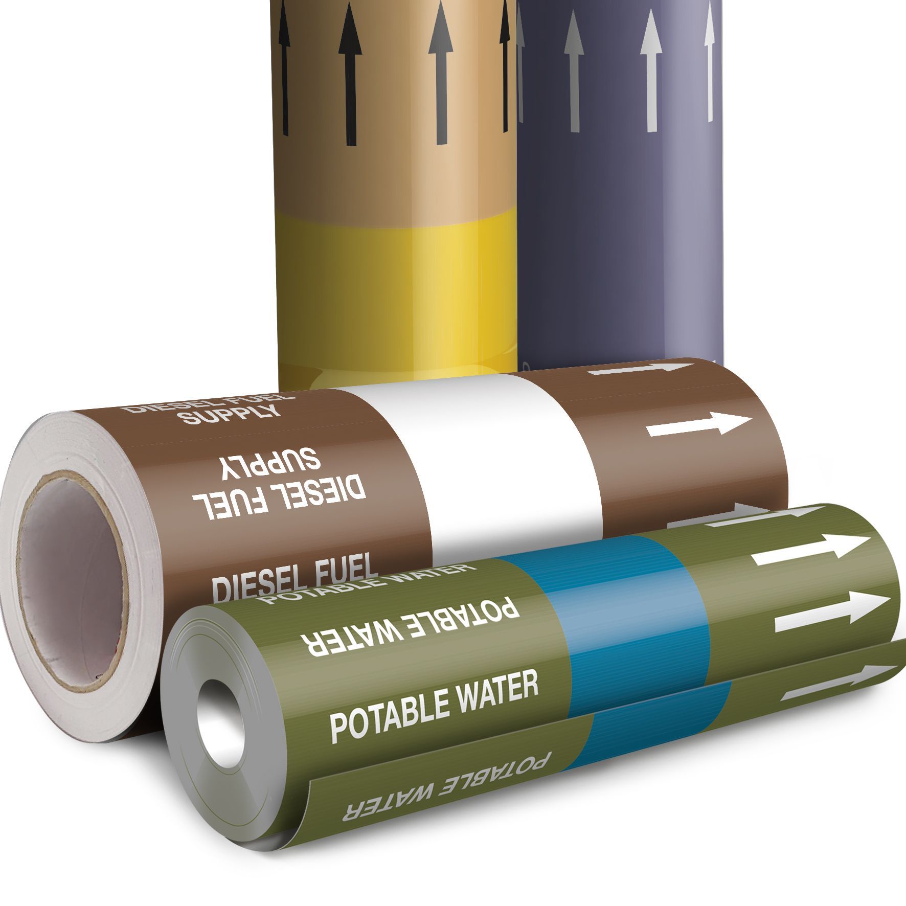
Identification through colour
The BS1710:2014 standard utilises a system of 8 Basic colours to identify the basic contents of the pipe, then further colour banding may identify quality, properties, uses and help to further distinguish the contents.
Basic Identification Colours (BIC)
Text provides specific content information and arrows show the direction of flow. Safety and code colours are applied in bands as explained further along in this article.
All colours are specified from BS4800
Safety Colours

Code & Other Colours
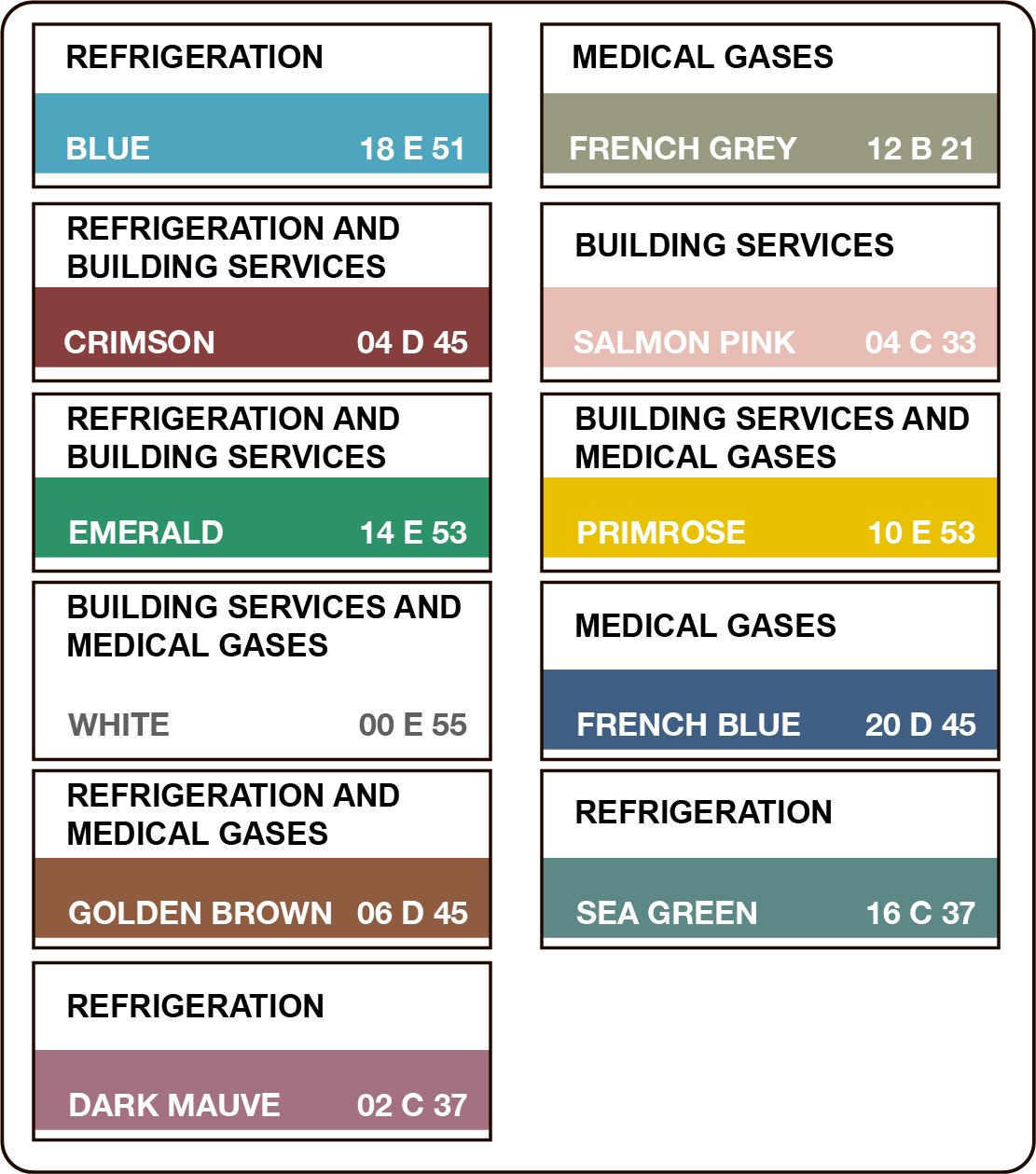
These colours are used when there are regulations that are required to be met in specific industries or in specific contexts. BS1710:2014 has incorporated these into the standards.
This means that the correct implementation of pipe marking according to BS1710:2014 will also ensure your pipe marking also meets the requirements of:
• Building Regulations (Parts L & G);
• F-Gas Regulations (EU/UK law)
• HTM 02-01 (UK NHS)
Alongside meeting the requirements of
Health & Safety (Signs and Signals) Regulations 1996.
Marker Sizes & Basic Marker Design Specifications
BS1710:2014 sets standards for design, size and positioning of colour coding markers on pipelines to ensure safety and compliance to the applicable regulations.
Sizes of Colour Coding Markers
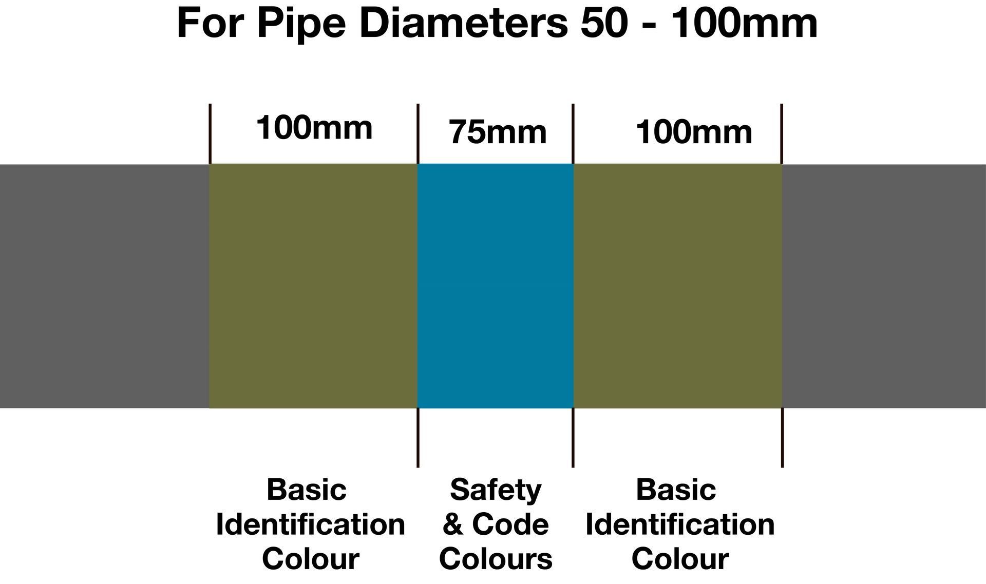
| Pipe Diameter <50mm | Pipe Diameter 50-100mm | Pipe Diameter >100mm | |
|---|---|---|---|
| Basic ID Colour | 50mm | 100mm | 150mm |
| Safety / Code Colours | 30mm | 75mm | 150mm |
| Total Marker Width | 130mm | 275mm | 450mm |
BS1710 sets out standards on the size of the colour banding required, dependant on the diameter of pipe being marked.
The diagram here shows the basic design principle of the banding.
- The Basic Identification Colour may be used alone in some circumstances and the BIC would constitute the whole of the total marker width.
- When Code and/or Safety Colours are to be used in the marker; it should follow the principle shown. The marker design should have the BIC equal on either side of the code or safety colours. The chart here shows the correct banding widths for the various pipe diameters.
To be compliant with the standard, you must use the correct size marking for the diameter of pipe being marked, include the thickness of any lagging in your calculations.
Supplementary information is also required by the standards such as direction of flow and the pipe contents described as text. PWUK
Text & Supplementary Information
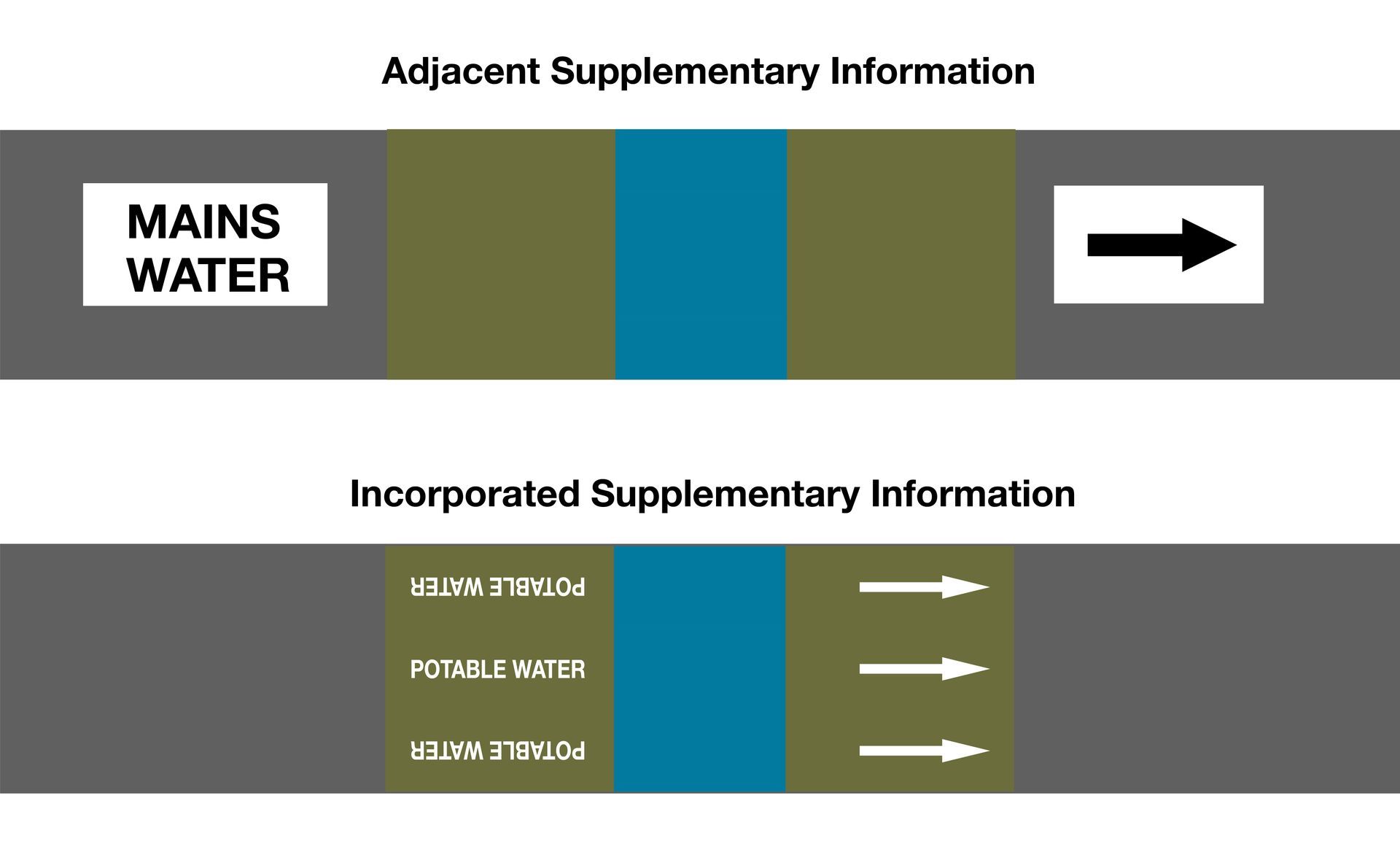
BS1710 requires supplementary information to the colour bands so that a pipe marker is unambiguous.
• Flow Direction Arrows
Mandatory if flow is not otherwise obvious
• Text Legend
Mandatory for all pipes. Must identify the contents in clear words. Can be any of, or a combination of the listed formats:
PWUK
• Name in Full,
• Abbreviation of Name
• Chemical Symbol
• Condition Data
Pressure / Temperature / Concentration where these factors are important for safety or operation, they must be included in the text legend.
Placement of BS1710 Pipe Markers in your Pipeline
BS1710:2014 sets standards for the placement of identifying markers. To be compliant with the standards; you must position markers wherever possible in the following indicated conditions and wherever else that identification is necessary for safety.
Conditions for identifying positions to place BS1710 pipe markers
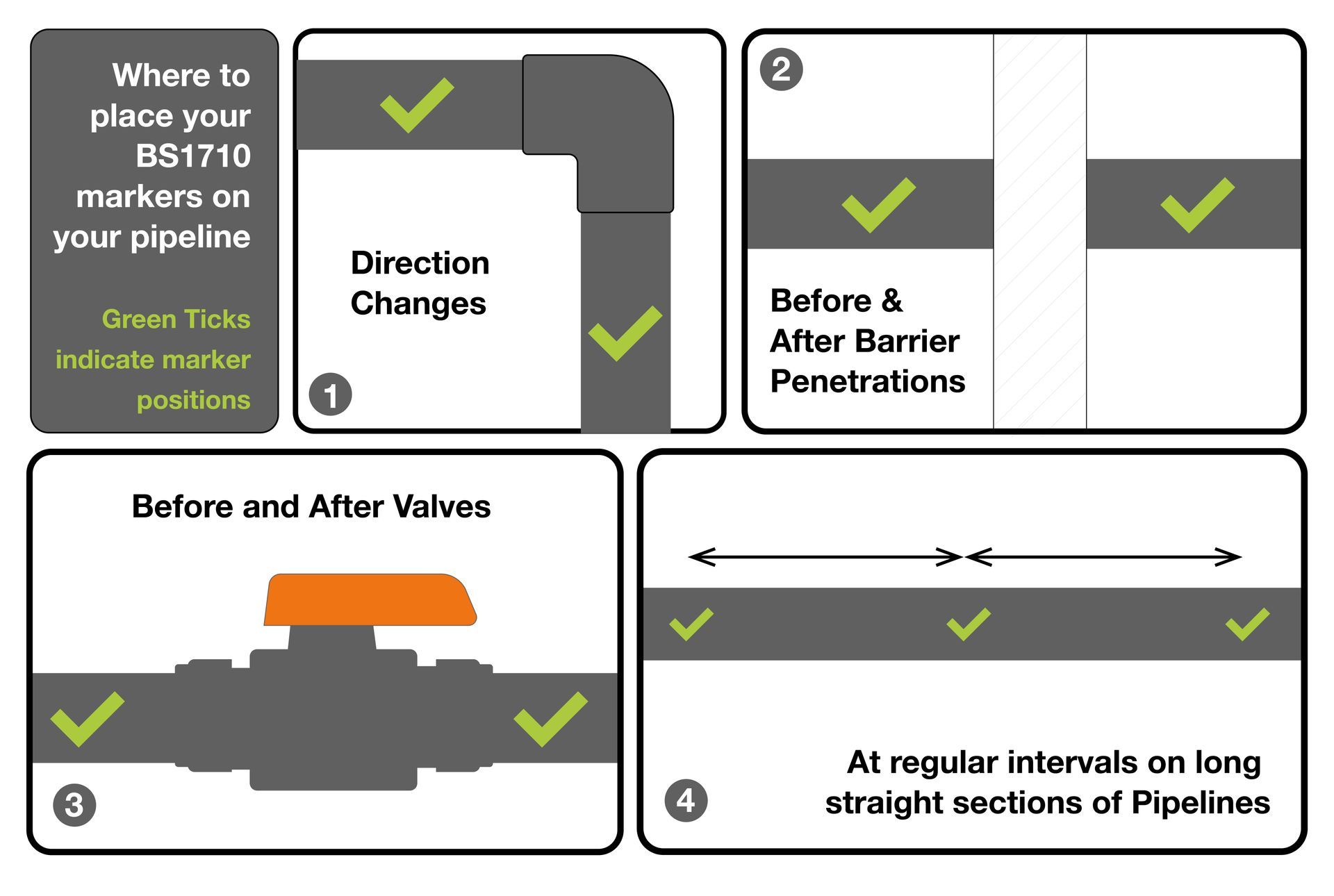
1 - Direction Changes
When the pipeline changes direction a marker should be placed
2 - Before and After Barrier Penetrations
This could mean as a pipe travels through a wall it would require a marker as it enters and exits, so that it is identifiable from both sides. This also applies to instances where a pipe travels through floor joists, a marker should be placed in every section between floor joists, to ensure identification no matter which area is exposed during future maintenance.
3 - Before & After Valves PWUK
Many systems have clusters of valves (manifolds, distribution headers, bypass loops) - Placing markers ensures every valve’s function is obvious at a glance. A marker after the valve confirms that the downstream leg carries the same substance (or indicates if it changes — e.g. mixing or branch lines). Markers at valves make emergency isolation fast and unambiguous.
4 - At Regular Intervals along straight sections of pipe
The BS1710:2014 doesn't specify a particular interval distance, but the common guidance adopted from the standard + HSE practice is:
- Every 3–5 m indoors (plantrooms, service corridors, workshops).
- Every 8–10 m outdoors (open pipe racks or where pipes are easily visible).
- Always within sight — a person standing anywhere along the pipeline should be able to see at least one identification marker.